Registruokitės, kad atrakintumėte savo išskirtines B2B kainas ir pradėtumėte apsipirkinėti. Užsiregistruokite dabar!
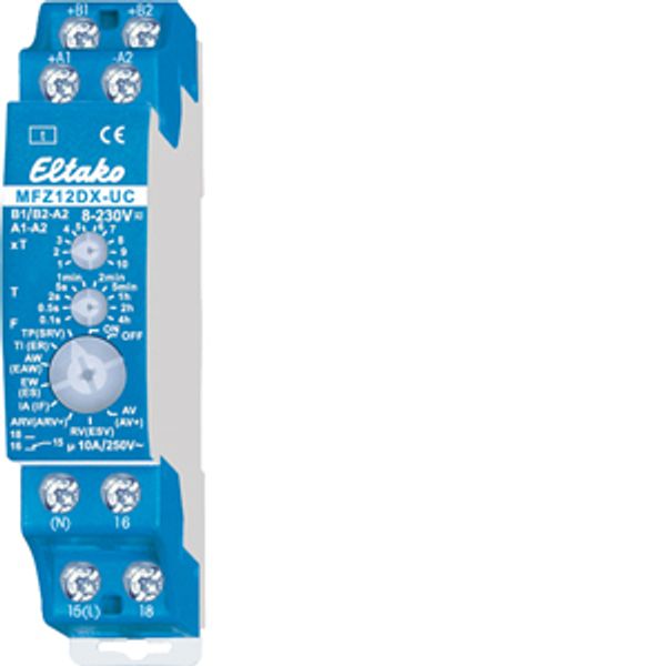
Analogue settable multifunction time relay 1 CO contact 10A
Yra sandėlyje: Ne
Pardavėjo atsargos: Ne
Minimalus užsakymo kiekis: 1
Kaina (be PVM):
44,38 €
EAN: 4010312603086
MPN: 23001005
Pakuotė: 1
Technical Information
| Prekės būklė | Nauja |
| Gamintojo pavadinimas | Analogue settable multifunction time relay 1 CO contact 10A |
| Prekės ženklas | ELTAKO |
| Kategorijos |
Relės
|
| Kilmės šalis | CN |
| Suderintos sistemos kodas | 8536 4900 00 |
| Montavimo metodas | DIN bėgis |
| Funkcija | Daugiafunkcinis |
| Suprojektuotas aukštis | 58 mm |
| Sužadinimo tipas | Analaginis su daug funkcijų |
| Modulinių tarpų skaičius plotyje | 1 |
| Perjungimo jungiklių skaičius | 1 |
| 1 kontrolinė įtampa | 8-230 V |
| 1 kontrolinės įtampos tipas | Kintamoji ar nuolatinė srovė |
| 1 kontrolinės įtampos dažnis | 50 Hz |
| Tiekimo įtampos tipas | Kintamoji ar nuolatinė srovė |
| Maitinimo įtampos diapazonas | 8-230 V |
| 1 intervalo vienetas | Minutės/ valandos |
| 1 intervalas nuo / iki | 0.1-40 |
| Kaitrinių lempų jungiklio pajėgumas | 2000 W |
| Fluorescencinės DUO lempos jungiklio pajėgumas | 1000 VA |
| Fluorescencinės indukcinės lempos jungiklio pajėgumas | 1000 VA |
| Fluorescencinės lygiagrečios lempos jungiklio pajėgumas | 500 VA |
| Įprastai uždarytų kontaktų skaičius | 0 |
| Įprastai atvirų kontaktų skaičius | 0 |
Pakavimo informacija
| Pakavimo lygis 1 | 4010312603086, 4010312603086 |
| Pakavimo lygis 2 | 4010312603086 |
| Pakavimo lygis 3 | 4010312603086 |
Atsisiuntimai
Aprašymas
1 CO contact potential free 10A/250V AC. 230V LED lamps up to 200W, incandescent lamps 2000W*. Standby loss 0.02–0.6 watt only. Modular device for DIN-EN 60715 TH35 rail mounting. 1 module = 18mm wide, 58mm deep. With the patented Eltako Duplex technology (DX) the normally potential-free contacts can still switch in zero passage when switching 230V AC 50Hz and therefore drastically reduce wear. Simply connect the neutral conductor to the terminal (N) and L to 15(L) for this. This gives an additional standby consumption of only 0.1 Watt. Universal control voltage from 8 to 230V UC. Supply voltage same as control voltage. Time setting between 0.1 second and 40 hours. By using a bistable relay coil power loss and heating is avoided even in the on mode. The switched consumer may not be connected to the mains before the short automatic synchronisation after installation has terminated. According to the connection of the power supply to the terminals B1-A2 or B2-A2 two different levels of settings can be selected: Functions F with connection of the power supply to B1-A2 (Standby loss 0.02-0.4W): RV = off delay. AV = operate delay. TI = clock generator starting with impulse. TP = clock generator starting with pause. IA = impulse controlled operate delay (e.g. automatic door opener). EW = fleeting NO contact. AW = fleeting NC contact. ARV = operate and release delay. ON = permanent ON. OFF = permanent OFF. Functions (F) with connection of the power supply to B2-A2 (Standby loss 0.02-0.6W): SRV = release-delay impulse switch. ER = relay. EAW = fleeting NO contact and fleeting NC contact. ES = impulse switch. IF = pulse shaper. ARV+ = additive operate and release delay. ESV = impulse switch with release delay and switch-off early-warning function. AV+ = additive operate delay. ON = permanent ON. OFF = permanent OFF. The LED below the big rotary switch indicates the contact position while time-out is in progress. It blinks while the relay contact 15-18 is open (15-16 closed), and is continuously ON as long as the relay contact 15-18 is closed (15-16 open). The time base T is selected by means of the middle, latching rotary switch T. Time-base figures available are 0.1 seconds, 0.5 seconds, 2 seconds, 5 seconds, 1 minute, 2 minutes, 5 minutes, 1 hour, 2 hours and 4 hours. The total time is obtained by multiplying the timebase by the multiplier. The multiplier xT is set on the upper, latching rotary switch xT and is in the range from 1 to 10. Thus, time settings can be selected in the range from 0.1 second (time base 0.1 second and multiplier 1) and 40 hours (time base 4 hours and multiplier 10). * The maximum load can be used starting at a delay time or clock cycle of 5 minutes. The maximum load will be reduced for shorter times as follows: up to 2 seconds 15%, up to 2 minutes 30%, up to 5 minutes 60%.

